|
|
 |
 |
 |
 |
> 자료실 > 기술자료실 |
 |
|
|
 |
|
|
| :: 관리자 |
2007-06-13 16:45:25 ,
조회 :322075 |
| |
::  File download [pdf : 20 KB Download: 7618]
 |
 |
|
|
| BETTER GROUNDING |
| |
Roy B. Carpenter Jr.,
Mark M. Drabkin & Joseph A. Lanzoni
Lightning Eliminators & Consultants, Inc., USA
May 1997 |
|
| |
A grounding system is an essential part of any electric/electronic
system. The objective of a grounding system may be summarized as follows:
1. To provide safety to personnel during normal and fault conditions
by limiting step and touch potential.
2. To assure correct operation of electrical/electronic devices.
3. To prevent damage to electrical/electronic apparatus.
4. To dissipate lightning strokes.
5. To stabilize voltage during transient conditions and therefore
to minimize the probability of flashover during the transients.
6. To divert stray RF energy from sensitive audio, video, control,
and computer equipment. |
As it is stated in the ANSI/IEEE Standard 80-1986 “IEEE Guide for
Safety in AC Substation Grounding,” a safe grounding design has two
objectives:
1. To provide means to carry electric currents into the earth under
normal and fault conditions without exceeding any operating and equipment
limits or adversely affecting continuity of service.
2. To assure that a person in the vicinity of grounded facilities
is not exposed to the danger of critical electric shock. |
| |
A practical approach to safe grounding considers the interaction
of two grounding systems: The intentional ground, consisting of ground
electrodes buried at some depth below the earth surface, and the accidental
ground, temporarily established by a person exposed to a potential
gradient at a grounded facility.
An ideal ground should provide a near zero resistance to remote earth.
In practice, the ground potential rise at the facility site increases
proportionally to the fault current; the higher the current, the lower
the value of total system resistance which must be obtained. For most
large substations the ground resistance should be less than 1 Ohm.
For smaller distribution substations the usually acceptable range
is 1-5 Ohms, depending on the local conditions.
The grounding system of power plants and substations is usually formed
by several vertical ground rods connected to each other and to all
equipment frames, neutrals and structures that are to be grounded.
Such a system that combines a horizontal grid and a number of vertical
ground rods penetrating lower soil layers has several advantages in
comparison to a grid alone. Sufficiently long ground rods stabilize
the performance of such a combined system making it less dependent
on seasonal and weather variations of soil resistivity. Rods are more
efficient in dissipating fault currents because the upper soil layer
usually has a higher resistivity than the lower layers. The current
in the ground rods is discharged mainly in lower portion of the rods.
Therefore, the touch and step voltages are reduced significantly compared
to that of the grid alone.
In areas where the soil resistivity is rather high or the facility
space is at premium, it may be not possible to obtain the required
low impedance of the grounding system by spreading the ground rods
and grid over a large area. The possible solutions of that rather
complicated problem may be summarized as follows:
1. To change the soil resistivity in the limited area of interest
by implementation of the chemically charged ground rods with or without
an additional backfill.
2. To establish remote ground grid connected to the main ground system.
3. To use the deep-driven ground rods reaching underground water table
or lower soil layers with low resistivity.
4. To use main/remote ground mats.
To analyze the technical and economical aspects of each one of alternatives
mentioned above, first one must examine the components of the grounding
electrode resistance.
There are three general components affecting grounding electrode resistance:
(1) The resistance of the electrode, (2) the resistance of the electrode-to-soil
interface area, and (3) the soil resistivity. |
| |
The resistance of the electrode itself is negligible,
although it varies with the length, diameter and deployment of the
electrode. The resistance of the electrode-to-soil interface
area is nearly negligible at temperatures above freezing.
However, when the temperature of soil drops below freezing point,
a veneer of ice may form on the ground
electrode, adding resistance to the electrode/earth interface. Another
that affects electrode/soil interface resistance is soil compactness
around the ground electrode. A loose backfill or non-compact soil
around the electrode will reduce the contact area and increase resistance.
The soil resistivity is the single most important factor
affecting the resistance of the ground system. That is why the most
economically sound solution is
lowering the soil resistivity to the level required to obtain the
specified resistance/impedance of the ground system. In order to work
out a practical approach of the soil treatment, the soil characteristics
related to electrical conductivity are to be studied. |
| Soil Characteristics |
Most soils behave both as a conductor of resistance R, and as a
dielectric. For high frequency and steep-front waves penetrating a
very high resistive soil, the earth may be presented by a parallel
connection of resistance R, capacitance C, and a gap. For low frequencies
and dc the charging current is negligible comparing to the leakage
current, and the earth can be presented by a pure resistance R.
A voltage gradient across the earth does not affect the soil resistivity
until the gradient reaches a certain critical value varying with the
soil material, but usually of several kilovolts per centimeter. If
the critical value of the voltage gradient is exceeded (in case of
lightning), an arc would develop at the electrode surface and progress
into the earth, increasing the effective size of the electrode, until
the gradients are reduced to the values that the soil can withstand.
Frequencies under about 30 MHz almost do not affect the impedance
of the earth’s surface layer, but the depth of penetration varies
with frequency f as (pfsm) -1/2 . The depth of penetration also depends
on the relative resistivity of earth layers below. Soil resistivity
is affected by the following five factors:
Soil
type. Soil resistivity varies widely depending on soil type,
from as low as 1 Ohmmeter for moist loamy topsoil to almost 10,000
Ohm-meters for surface limestone.
Moisture content
is one of the controlling factors in earth resistance because
electrical conduction in soil is essentially electrolytic. The resistivity
of most soils rises abruptly when moisture content is less than 15
to 20 percent by weight, but is affected very little above 20 percent.
It must be recognized, however, that the moisture alone is not the
predominant factor influencing the soil resistivity. If the water
is relatively pure, it will be of high resistivity and may not provide
the soil with adequate conductivity.
The soluble
salts, acids or alkali presented in soil influence considerably
the soil resistivity. The most commonly used salting materials are
sodium chloride (common salt), copper sulfate and magnesium sulfate
(Epsom salt). Different types of salts have varying depletion rates;
consequently, different types may be combined to produce the optimum
depletion and conditioning characteristics. Sodium chloride and magnesium
sulfate are the most commonly used salting materials. Magnesium sulfate
is considered to be the least corrosive. Salting materials will inhibit
the formation of ice and will lower the resistivity of the soil. It
may take some time for the salting effects to be noticed, although
the earth connection will continue to improve over time until the
salt content reaches about six per cent by weight. Higher resistivity
soils take longer to condition. It takes topsoil about two months,
clay four months and sand/gravel five months for the salt minerals
concentration to reach about six per cent. Such concentration of salts
poses a negligible corrosion threat.
The temperature
effect on soil resistivity is almost negligible for temperatures above
the freezing points. When temperature drops below water freezing point
the resistivity increases rapidly.
Compactness and
granularity affects soil resistivity in that denser soils
generally have lower resistivity. These factors do not vary over time.
Once the resistivity has been assessed these factors can usually be
ignored.
From all the factors mentioned above, two factors?moisture and salt
content?are the most influential ones on soil resistivity for a given
type of soil. Therefore the chemical treatment of soil surrounding
ground rods is preferable and in some cases the only economically
sound solution in obtaining low impedance of the ground system. |
| Grounding with Chemically Charged
Rods |
The chemical treatment of the soil surrounding the ground electrodes
may be implemented by any one of the following three ways:
1. To use conductive backfill materials. Several materials exist on
the market that are used to replace poorly conducting soil near the
ground electrodes. The impact of putting these materials around the
electrodes is significant, since that is where the majority of connection
to the earth takes place. Four such materials used for conductive
backfills around ground electrodes are described below.
Concrete has a resistivity range of 30 to 90 Ohm-meters.
Since it is hydroscopic by nature it will tend to absorb moisture
when available and keep it up to 30 days, thus maintaining a resistivity
lower than the surrounding soil. However, during a long dry season
concrete will dry out with a subsequent rise in resistivity. Also,
if a substantial
amount of fault or lightning current is injected into a concrete encased
electrode, the moisture in the concrete may become steam, dramatically
increasing in volume and placing a substantial stress on the concrete.
Bentonite is a naturally occurring clay
with a resistivity of about 2.5 Ohm-meters. It used widely as a conductive
backfill material. Like concrete it is hydroscopic, which makes it
subject to the same drying out concern as concrete. Expansion range
of bentonite can reach 300 percent, which means that in dry situations
it can shrink away from an electrode, resulting in substantial increase
of ground resistance.
Clay-based backfill mixtures
have generally a resistivity lower than pure bentonite due to the
addition of carbon or/and other minerals that provide a greater spectrum
of electrically conducting materials. Because these mixtures are clay-based
they retain their hydroscopic character to some degree, while the
blending of materials dampens the resistance variability with respect
to moisture.
Carbon-based backfills materials
have generally a resistivity lower than clay-based mixtures. Some
of these materials can be mixed with concrete to make concrete more
conductive. However, these materials tend to be the most expensive
and do not retain moisture nearly as well as clay-based materials.
The amount of the backfill material required is determined in most
cases by the Interfacing Volume and Critical Cylinder principles.
A ground electrode establishes a connection to earth by affecting
only a certain volume of earth, called the Interfacing Volume (IV).
For practical purposes for a ground rod the entire connection to earth
is
contained within an IV whose radius is 2.5 times the length of the
rod. Most of the earth connection takes place in a cylinder close
to the electrode, called the Critical Cylinder. A study of the influence
of soil within the IV demonstrates that six inches of soil along any
radial makes up 52 per cent of the connection to earth; a 12 inches
makes up 68 percent of the connection. Beyond a diameter of 24 inches
there is very little improvement for
much larger diameters. Therefore, the recommended diameter for the
Critical Cylinder is between 12 and 24 inches, and the calculated
amount of the required backfill material is based on that diameter
and the length of the ground rod. |
2. To use the chemically charged ground rods (CCGR) instead of the
conventional ground rods. A CCGR is a copper tube of 2-2.5 inches
in diameter with several small holes perforated along the length of
the tube. The tube is filled with metallic salt evenly distributed
along the entire length of the tube. The moisture absorbed from the
air and soil form a solution of the contained metallic salt within
the CCGR which seeps out through the holes into the surrounding soil,
thus lowering the soil’s resistivity and increasing the efficiency
of the electrode. Figure 1 illustrates the concept of the CCGR.
Table 1 presents the comparison of the measured grounding resistance
of five different ground rods in five different soils with resistivity
varying from 9 Ohm-meters to 30,000 Ohm-meters. The last two rows
in that table represent performance of the different types of CCGR
and clearly achieve the lowest resistance as compared to the conventional
types of ground rods with or without conditioning of the soil.
Automated mineral enhancement will permit the achievement of low resistance
as long as there is enough moisture available. It does, however, take
time for these automated enhancement system to achieve their goal.
That time depends on porosity of the soil.
Figure 2 shows the variations in the resistance of the CCGR as a function
of time. It is evident from that figure that the CCGR required about
ten weeks to reach the initial plateau. After that, resistivity continues
to drop off at a slower rate for six months or more, depending on
soil porosity. The resistance will decrease even during the dry
season. |
3. To implement a combination of the CCGR with backfill. This ground
system demonstrates the excellent stability over numbers of years
in keeping ground resistance permanently at a low fixed level. The
following example presented in Table 2 illustrates the economical
advantage of employing the CCGRs with backfills instead of
conventional grounding technique with ground rods and grids. Table
2 shows results of cost estimation for ground system of 1 and 5 Ohms
respectively in a dry sand and gravel soil with resistivity of 500
Ohm-meters.
As may be seen from that table, the grounding system based on the
implementation of the CCGRs with backfill appears to be the most economical
solution in the given conditions of poor conducting soil and low values
of the required ground resistance, even without taking into consideration
the cost of real estate. Where the appropriate space is not available
or too expensive, the CCGRs the only solution in establishing required
ground system. |
| Conclusions |
1. The CCGR establishes a relatively low ground resistance and ground
impedance which are not subjected to seasonal and weather variations.
2. The use of chemically charged ground rods, with or without backfill,
instead of conventional ground rods offers the most cost effective
design of any grounding system where the soil has a high resistivity
and/or where the space available for grounding is at
premium. |
|
|
|
|
|
| |
|
::
File download [pdf : 20 KB Download: 7618] |
|
|
|
|
 139 139 |
|
|
| Copyright © 1998-2015 by Ground.Co., Ltd., All rights reserved. |
|
|
 |
|
|
 eca3G 성능인증(EPC)획득
 낙뢰방호 현장설계모음
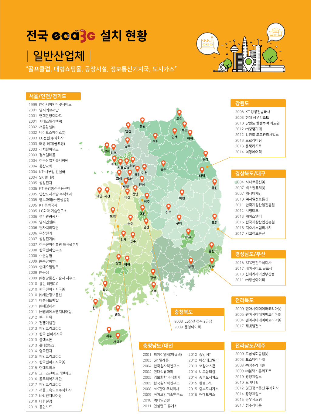
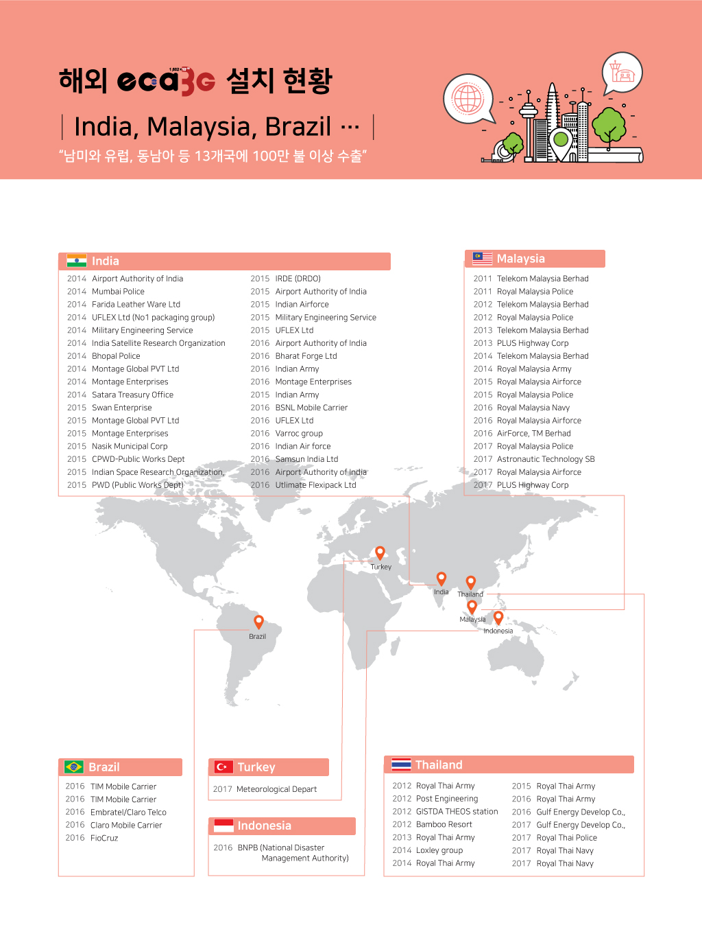
 주요 실적
주요 실적
 낙뢰 피해대책


